|
4. Evaluation
Procedure
Description
On the information level, how do we understand a neuron is transferring
information?
We will overview the different steps of the flow of information between
neurons.
We will also review the three means to control the flow of information.
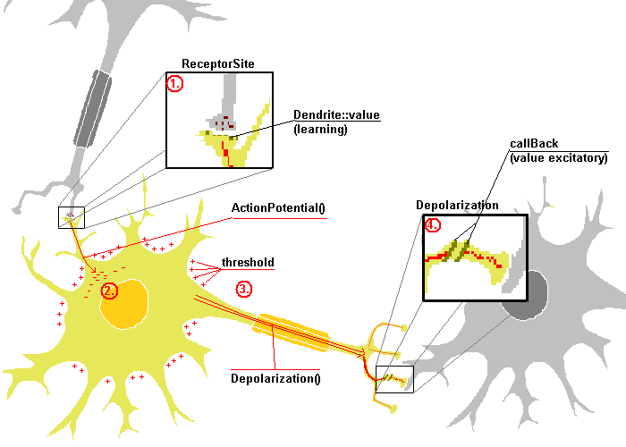
As described in the schema above, we distinctly notice the flow of
information passing from the dendrite to the synaptic knob via the soma.
- The dendrite will receive the information via the call of
ReceptorSite() and will transfer that amount after multiplying it
by the learning factor. We understand that the learning value is
the only value that can as well increase than decrease the signal of
information. This is why it is considered as the learning value.
- After having interpreted the excitation received thanks to the
learning ratio, the dendrite transfers the information to the Soma. That
action is called ActionPotential(). The action potential will store
the information in the Soma and inform the caller that a spike may or may
not be triggered.
- The soma can be depolarized iif the amount of information is bigger
than the threshold value. if so. it calls Depolarization() that
will transfer the amount of information to each of the synaptic knob. We
will only spike the different between the threshold and the amount of ions
stored in the soma.
- For the synaptic knob to interpret the Depolarization, they will call
a function to generate excitatory and inhibitory information - that ratio
is kept as the value of the object. That value may reduce the
importance of the information to be transferred to the next neuron
We are confronted with three different types of connection with the
Synaptic Knobs. It can connect to
- A Dendrite. This is considered as the basic trivial case. We
can increase or decrease the quantity of information to be transferred to
the Soma. The ratio is namely called the learning rate of the neuron for a
determined process. By this way the process may adapt this ratio to alter
the information in order to produce an expected result.
- A soma to alter the threshold value of the neuron. We will be able to
modify dynamically the threshold - we can then alter and control the
amount of information the neuron can resists before spiking. This can be
seen as a filter. (Note that after a certain amount of time the
information hold in the neuron will be lost).
- Another synaptic knob (Cfr
Synaptic Knob of the
object structure). The emission of neuron transmitters excitatory and
inhibitory will allow to produce complex logic.
As the mathematic model of neural network allows via the weight of the
links between neurons to transfer some positive or negative values. I really
do not see how the dendrite will generate some positive ionization in the
soma....
Our Neural entity will only deal with an existing or non existing amount
of information - No negative amount of information as this one does not
exist naturally.
Didactic
We will first overview the flow of some basic Boolean operation in a
didactic form. Later on we will attempt to simulate a more biological
behavior using less neurons.
The OR
To implement the OR Boolean, we only need 3 neurons: two inputs and one
output. The OR can easily be simulated as followed. The receiver (neuron in red) has two dendrites with the factor or 0.5 and
a threshold of the soma of 0.5 (the value is there in order to make sure
that any small values will not come to interfere)
The AND
With that sample, it is really easy to simulate and AND gate: simply put
the threshold of the receiver to 1.0 instead of 0.5.
I would consider the and as the base logical interaction of this neural
entity as it is the natural flood of the information thru the neurons
The NOT
This is how we can easily create a spike with a decision source
that is not sending any information. This is an excellent example of the use of the synaptic knob inhibitory
neurotransmitters: the synaptic knob when charged from the spike of the soma
with one unit simply produce excitatory neurotransmitters - should it be
charged with more than a unit it produces the surplus not with excitatory
but inhibitory neurotransmitters <=> a load of 2 will be resumed by the
generation of one unit of excitatory that will be annihilated by the one
unit inhibitory produced as surplus. (for example should it receive 1.5, the
amount of excitatory will be 1 and .5 of inhibitory resulting of an amount
of 1 - .5 = .5 sent).
The EOR operator is a two pass operator in the example hereby.
We are decomposing the EOR as ~( ~ (a + b) + (a . b)) (NB: the (a + b ) .
~(a . b) formula has the advantage of creating an EOR directly but it is
just for didactic purposes that I have chosen this one could have been
another)
Pass 1 : (a . b) and ~(a + b)
The two inputs are send to the and process and the or then Not processes.
At that stage the ans neuron is the A NOR B operator.
Pass 2 : ~ ((NOR) + (AND))
the second pass is reinserting the result of the and and the nor in the
same OR process
Note that the or neuron receives the NEOR operator at the second pass
We will here decrease the amount of neuron: in fact the synaptic knob of
a neuron can be connected to one one of its own dendrite, reducing the
amount of neuron. The idea make the neuron (E.g. the Boolean-OR neuron) the
second part but also the receptor of the operation allowing a far bigger
flexibility in the manipulation of neurons. The C++ code is available
to download at the site under the file name test1-bio.cpp.
This simple OR gate shows how easily this can be implemented. This
solution also is pretty intuitive. Indeed we can understand the schema as
followed: Input 1 OR input 2 and naturally we will expect a result in the
Input 2 neuron as it is ored with the input 1. The equivalent in C is In2
|= In1;
The same logic can also be applied for the AND gate and the NOT
gate.
The NAND or NOR gate could be interpreted as such.
This does not affect the result in In2 as the (OR or AND) and the trigger is
as seen a real inverse operator and does it all.
This aspect of the NOT will allow us to create a Inverse Neuron that will
automatically set itself up during depolarization call.
The only action we have to take care is to depolarize In2 twice: once to
receive the operator value and a second time to inject it into the trigger
to receive the Not value.
The EOR gate is quite easier to implement and also much more
intuitive than the normal Boolean operator formula. Thanks to the call back
(synaptic knob generating as much inhibitors than there are excitatory above
a certain amount) we are able to generate a real simple eor gate.
Let us follow and see what is happening with the possible values these
two neuron will have.
| In 1 |
In 2 |
Received by the call
back |
back to In2 |
| 0 |
0 |
0 |
0 |
| 0 |
1 |
1 |
1 |
| 1 |
0 |
1 |
1 |
| 1 |
1 |
2 (1 unit of excitatory and one unit of
inhibitory) |
0 |
This simple Boolean function describes a nice example of the connection
types:
The 'always 1' neuron synaptic knob is connected to the synaptic knob of
the 'In B'. The 'In B' Synaptic knob will generate inhibitor
neurotransmitters of the amount of information he is request to transmit
otherwise it just let the 'always 1' transmit thru him the information. The
'In C' has its threshold set to 1 by the same 'always 1' neuron (we can also
imagine a neuron having its threshold set as the result of an important
computation. This is how we intend to simulate the inference of one
importance process to a higher level Cfr
Learning
Procedure.
|